Wednesday, December 28, 2011
Saturday, December 17, 2011
Haagring's Formula Mini Cooper

The only allowed mods are: tires, bearings, t-bar (kyosho carbon only), and any body modification that doesn't affect exterior appearance (including modifying the original front body clip).
After some flipping and rolling runs all cars are now manageable and competitive. Lap times are 15 to 20% higher than the track's fastest lap though.
Monday, November 28, 2011
New Venue, New Layout

Tuesday, August 2, 2011
New Additions to Haagring's Fleet


Saturday, June 4, 2011
Thursday, June 2, 2011
Virtual Wind Tunnel: June 02, 2011 Update
This is a general update on all the recent CFD "virtual wind tunnel" simulations of a Kyosho Mini-Z MR03 Mazda 787b 3D model.
In addition to the configurations tested previously (no wing, flat rear wing, 15, 30, 45 and 60 degree rear wing) three additional ones were considered: broken wing, gurney flap, and scoop wing.
The table below shows drag and down forces for all the different rear wing configurations tested:
Drag (gf)
|
Down Force (gf)
| |
No Rear Wing
|
6.2
|
- 7.8 (lift)
|
Broken Wing
|
6.4
|
- 3.8 (lift)
|
0o Rear Wing
|
6.6
|
- 0.5 (lift)
|
15o Rear Wing
|
7.7
|
4.6
|
Gurney Flap
|
7.2
|
5.7
|
30o Rear Wing
|
8.9
|
8.0
|
45o Rear Wing
|
10.1
|
8.5
|
60o Rear Wing
|
10.6
|
9.3
|
Scoop Wing
|
11.7
|
13.5
|
A chart showing these results, and the trade off between drag and down forces, is available here.
All values above consider the car "racing" at 10 m/s (36 km/h). Charts showing the results for other speeds (2.5, 5.0, 7.5 in addition to 10 m/s) are available here.
Detailed results and pictures for each of the simulations are posted in the following links:
Virtual Wind Tunnel: No Rear Wing
Virtual Wind Tunnel: Broken Rear Wing
Virtual Wind Tunnel: Flat Rear Wing
Virtual Wind Tunnel: 15 Degree Rear Wing
Virtual Wind Tunnel: Broken Rear Wing
Virtual Wind Tunnel: Flat Rear Wing
Virtual Wind Tunnel: 15 Degree Rear Wing
Virtual Wind Tunnel: 60 Degree Rear Wing
Virtual Wind Tunnel: Scoop Wing
Virtual Wind Tunnel: Scoop Wing
Streamlines, pictures showing the theoretical trajectory of particles flowing around the car are posted here (colored according to pressure coefficient - Cp) and here (colored by air speed).
Videos of vertical plane streamlines, "3D" streamlines and particle tracks are also available.
Once again, all results come from a computer simulation of a Kyosho Mini-Z MR03 3D model, resembling a Mazda 787b car body. None of the results have been validated empirically at a real wind tunnel, so all the typical CFD caveats apply.
Once again, all results come from a computer simulation of a Kyosho Mini-Z MR03 3D model, resembling a Mazda 787b car body. None of the results have been validated empirically at a real wind tunnel, so all the typical CFD caveats apply.
Wednesday, June 1, 2011
Virtual Wind Tunnel: Scoop Wing
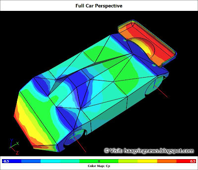
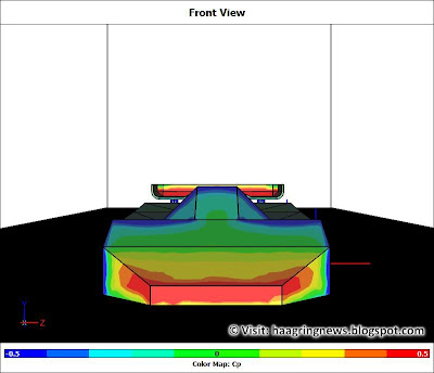
These are the results of a CFD "virtual wind tunnel" simulation of a Kyosho Mini-Z MR03 Mazda 787b 3D model with a scoop wing.
The drag force recorded by the simulation while the car was "racing" at 10 m/s (36 km/h) was 11.7 gf. The down force recorded by the simulation at this speed was 13.5 gf.
The pictures below show the pressure coefficient (Cp) indicating high (red) and low (blue) pressure areas.


For complete results of the Mini-Z MR-03 CFD "virtual wind tunnel" simulation click here.
The drag force recorded by the simulation while the car was "racing" at 10 m/s (36 km/h) was 11.7 gf. The down force recorded by the simulation at this speed was 13.5 gf.
The pictures below show the pressure coefficient (Cp) indicating high (red) and low (blue) pressure areas.


Virtual Wind Tunnel: Gurney Flap
These are the results of a CFD "virtual wind tunnel" simulation of a Kyosho Mini-Z MR03 Mazda 787b 3D model with a 4 mm gurney flap.
The drag force recorded by the simulation while the car was "racing" at 10 m/s (36 km/h) was 7.2 gf. The down force recorded by the simulation at this speed was 5.7 gf.
The pictures below show the pressure coefficient (Cp) indicating high (red) and low (blue) pressure areas.


For complete results of the Mini-Z MR-03 CFD "virtual wind tunnel" simulation click here.
The drag force recorded by the simulation while the car was "racing" at 10 m/s (36 km/h) was 7.2 gf. The down force recorded by the simulation at this speed was 5.7 gf.
The pictures below show the pressure coefficient (Cp) indicating high (red) and low (blue) pressure areas.


Virtual Wind Tunnel: Broken Wing
I broke the rear wing of my real Kyosho Mini-Z MR03 Mazda 787b last night while racing at Haagring. So I decided, just for fun, to run a CFD "virtual wind tunnel" simulation of a broken rear wing.
The results were the following: the drag force recorded by the simulation while the car was "racing" at 10 m/s (36 km/h) was 6.4 gf. The down force recorded by the simulation at this speed was - 3.8 gf, that is, 3.8 gf of lift. No significant lateral forces were measured, in spite of the asymmetric wing configuration.
The pictures below show the pressure coefficient (Cp) indicating high (red) and low (blue) pressure areas.


For complete results of the Mini-Z MR-03 CFD "virtual wind tunnel" simulation click here.
The results were the following: the drag force recorded by the simulation while the car was "racing" at 10 m/s (36 km/h) was 6.4 gf. The down force recorded by the simulation at this speed was - 3.8 gf, that is, 3.8 gf of lift. No significant lateral forces were measured, in spite of the asymmetric wing configuration.
The pictures below show the pressure coefficient (Cp) indicating high (red) and low (blue) pressure areas.


Tuesday, May 31, 2011
Virtual Wind Tunnel: Streamlines U (Air Speed)
The pictures below show the streamlines for the CFD "virtual wind tunnel" simulation of a Kyosho Mini-Z MR03 Mazda 787b 3D model, "racing" at 10 m/s (36 km/h).
In this type of simulation a streamline is the theoretical path that a particle flowing around the vehicle would describe.
There are five different pictures, one for each of the following rear wing configurations: no wing, flat wing, 45 degree wing, gurney flap, scoop wing.
Both the car and lines are colored according to the air speed. Red represents high air speed (11 m/s) and blue represents low air speed (5 m/s).
 |
No Wing - Air Speed |
 |
Flat Wing - Air Speed |
 | ||||
45 Degree Wing - Air Speed
|


Monday, May 30, 2011
Virtual Wind Tunnel: Streamlines Cp (Pressure Coefficient)
The pictures below show the streamlines for the CFD "virtual wind tunnel" simulation of a Kyosho Mini-Z MR03 Mazda 787b 3D model, "racing" at 10 m/s (36 km/h).
For complete results of the Mini-Z MR-03 CFD "virtual wind tunnel" simulation click here.
In this type of simulation a streamline is the theoretical path that a particle flowing around the vehicle would describe.
There are five different pictures, one for each of the following rear wing configurations: no wing, flat wing, 45 degree wing, gurney flap, scoop wing.
Both the car and lines are colored according to the pressure coefficient (Cp). Red represents higher pressure regions, blue represents lower pressure ones.
 |
| No Wing - Cp |
 |
| Flat Wing - Cp |
 |
| 45 Degree Wing - Cp |
 |
| Gurney Flap - Cp |
 |
| Scoop Wing - Cp |
For complete results of the Mini-Z MR-03 CFD "virtual wind tunnel" simulation click here.
Saturday, May 28, 2011
Virtual Wind Tunnel: Forces vs. Speed
The charts below show the results of a CFD "virtual wind tunnel" simulation of a Kyosho Mini-Z MR03 Mazda 787b 3D Model.
The first chart shows the increase in drag force as a function of speed. The second chart shows the relationship between down force (or lift) and speed. Both charts show the data points and curves for each one of the different rear wing configurations tested in the simulations: no rear wing, flat rear wing, 15 degree rear wing, 30 degree rear wing, 45 degree rear wing, 60 degree rear wing, gurney flap, scoop wing.
Each data point on each chart represents a different simulation, conducted at a different speed: 2.5 m/s (9km/h), 5.0 m/s (18 km/h) , 7.5 m/s (27 km/h), and 10 m/s (36 km/h). This should cover practically the full range of speeds observed in a typical Mini-Z track.
The curves were interpolated using a 2nd order polynomial. In all cases the fit was almost perfect (R-squared greater than 0.98) indicating that, according to the simulation, both drag and down forces increase as a proportion of speed squared. These results are pretty much in line with basic aerodynamics laws.


For complete results of the Mini-Z MR-03 CFD "virtual wind tunnel" simulation click here.
Virtual Wind Tunnel: Drag vs. Down Force Trade Off
The chart below shows the overall results for a CFD "virtual wind tunnel" simulation of a Mini-Z MR03 Mazda 787b 3D model, "racing" at 10 m/s (36 km/h).
Each data point on the chart corresponds to a different rear wing configuration: no rear wing, flat rear wing, 15 degree rear wing, 30 degree rear wing, 45 degree rear wing, 60 degree rear wing. Also on the chart are the results for a gurney flap and for a scoop wing. The drag force for each configuration is shown on the horizontal axis. The vertical axis shows the down force (or lift, for negative values). All forces are shown in gf.

According to the simulation results, there is a clear benefit of using practically any type of wing, even a flat one. This benefit comes from neutralizing the lift effect generated by the body shell itself. The greater the angle of the rear wing, the greater the benefit in terms of down force. This benefit, however, comes at the cost of increased drag.
The results indicate that, for the wing geometries tested, the sweet spot in terms of the drag vs. down force trade off might be close to the 30 degree configuration. Above that, increases in rear wing angle seem to bring only marginal improvements in down force while still increasing drag.
A gurney flap, according to the simulation, might be a good alternative providing a down force between the 15 and 30 degree wings with less drag.
A scoop wing configuration is the clear choice in terms of down force alone but, at the same time, it is the one with the highest drag.
For complete results of the Mini-Z MR-03 CFD "virtual wind tunnel" simulation click here.
Virtual Wind Tunnel: May 28, 2011 Update
This is a general update on all the recent CFD "virtual wind tunnel" simulations of a Kyosho Mini-Z MR03 Mazda 787b 3D model.
In addition to the configurations tested previously (no wing, flat rear wing, 45 degree rear wing) three additional ones were considered: 15 degree, 30 degree, and 60 degree. This gives a pretty complete range of rear wing angles and may help understand aerodynamic effects at the Mini-Z scale and speed.
In order to make the results comparable I had to re-design the previously tested 45 degree configuration and run the simulation again. As the results changed I updated the previous posts, so all published results are consistent and comparable.
The table below shows drag and down forces for the different rear wing configurations tested:
Detailed results and pictures for each of the simulations are posted in the following links:
Virtual Wind Tunnel: No Rear Wing
Virtual Wind Tunnel: Flat Rear Wing
Virtual Wind Tunnel: 15 Degree Rear Wing
Virtual Wind Tunnel: 30 Degree Rear Wing
Virtual Wind Tunnel: 45 Degree Rear Wing
Virtual Wind Tunnel: 60 Degree Rear Wing
In addition to the configurations tested previously (no wing, flat rear wing, 45 degree rear wing) three additional ones were considered: 15 degree, 30 degree, and 60 degree. This gives a pretty complete range of rear wing angles and may help understand aerodynamic effects at the Mini-Z scale and speed.
In order to make the results comparable I had to re-design the previously tested 45 degree configuration and run the simulation again. As the results changed I updated the previous posts, so all published results are consistent and comparable.
The table below shows drag and down forces for the different rear wing configurations tested:
Drag (gf)
|
Down Force (gf)
| |
No Rear Wing
|
6.2
|
- 7.8 (lift)
|
0o Rear Wing
|
6.6
|
- 0.5 (lift)
|
15o Rear Wing
|
7.7
|
4.6
|
30o Rear Wing
|
8.9
|
8.0
|
45o Rear Wing
|
10.1
|
8.5
|
60o Rear Wing
|
10.6
|
9.3
|
All simulations were done considering the car "racing" at 10 m/s (36 km/h).
Once again, all results come from a computer simulation of a Mini-Z 3D model, resembling a Mazda 787b car body. None of the results have been validated empirically at a real wind tunnel, so all the typical CFD caveats apply.
Virtual Wind Tunnel: Flat Rear Wing
Virtual Wind Tunnel: 15 Degree Rear Wing
Virtual Wind Tunnel: 30 Degree Rear Wing
Virtual Wind Tunnel: 45 Degree Rear Wing
Virtual Wind Tunnel: 60 Degree Rear Wing
Subscribe to:
Posts (Atom)